Hi there, welcome to my blog - La Revolution Deux. It's an odd name - but I like it! Here you will find all the info on my various DIY Guitar effects builds, amplifiers and guitars. Everything from a humble Ibanez tubescreamer to the holiest KLON Overdrive.
You may also find a few effects builds that I am looking to move on - usually in exchange for other effects/gear/cash. You can always check my ebay account to see what I've got up for grabs.
Have fun, enjoy the blog - Fred Briggs :-)
CONTACT ME
Feel free to get in contact with me about anything you see on this blog or with any general questions about guitars, amplifiers and effects, I'll be happy to answer! Just click the button above to email me directly or alternately my email address is fredbriggs2007 [at] googlemail [dot] com
I like collecting BJFe designs, I like their simplicity and the fact that they sound really good. Here's one of Bjorn's latest offerings - the Baby Pink Booster.
Here's the description from the Bearfoot FX website;
"+15 dbs of clean guitar friendly boost and a tasty buffer ... Deluxify your drives ! If you've seen the very expensive BJFe Honey Bee and Baby Blue and Emerald Green 'Deluxes' .... this is whats in there besides the drive circuit ---- the BPB is the buffer and the boost for those ---- so put the BPB at the end of your dirt section and 'Deluxe' them all. 8-18v for more headroom and clarity if needed"
Gutshot of the Bearfoot Baby Pink Booster
And, as usual, a YouTube clip of the offending pedal "in action" alongside some late 80s haircuts;
And here's the schematic provided by mmolteratx;
There you go, a simple jfet setup that runs at unity gain without the boost pot wiper connected to ground and boosts when the effect is engaged. For most fun - run this thing from 18 volts for extra gain and fun. You'll need to select the jfet as to get it biased correctly, go for one that gives you around 4.5v on the drain (or just one you like the sound of).
For more info and a few vero layouts check out this thread at freestompboxes.org; http://freestompboxes.org/viewtopic.php?f=7&t=22020
*This page also has a schematic for the Fred Briggs Rangemaster*
So, we all know there are many vintage treble/bass booster designs out there that were developed in the 1960s which were designed to give your tube amp the extra kick it needed to get some lovely tube saturation. Even with the huge number of modern stompboxes that promise to give you the ultimate booster people still love the old designs and cherish the tones they provide. But here's the problem; the increasing rarity of the key germanium transistors which are required to give them their original vintage vibe. Anyone who has built a germanium based pedal recently can testify that finding germanium transistors with the correct gain and leakage characteristics can be a frustrating (and expensive!) experience.
So, what to do? Easy, come up with a new design that still gives all those vintage tones but uses easy to source parts. However, before we start lets have a look at some of the more popular vintage boosters that are out there. Firstly the legendary Dallas Rangemaster:
And the Apollo Treble/Bass booster:
The Hornby Skewes Selectatone Treble/Bass Booster:
The Hornby Skewes Treble Booster:
This unit also built with an OC44 Ge Transistor
And the Orange / Vox / Apollo Treble/Bass Booster:
Ok, so what am I suggesting we do? Find some germanium, that's what we need to do - easily obtainable germanium. Impossible? No. The Russians were using germanium for a long time after the West stopped and their production methods produced transistors that were a lot more consistent than our attempts.
For example I have a pack of 50 MP14b transistors I bought on a whim from ebay for about £10. I tested them all and 95% of them came back good with gains from 25-40hfe and leakages of less than 200mA (most were less than 100mA!). Very nice, but the gains are a little low. Luckily there is a little trick in transistor land called the "darlington configuration": http://en.wikipedia.org/wiki/Darlington_transistor
Configuring transistors like in essence creates a single transistor which has a gain equal to the product of the gain's of the two individual transistors. Ok, so if I have two transistors each with a gain of only 25hfe I end up with one transistor with a gain of 625... Hmmm, far too much, but there is a way to force the circuit to think the gain is lower. Pete Moore of Diystompboxes.org did this:
Using a low gain (~50hfe) OC44 and a medium gain silicon transistor) he created a hybrid Rangemaster he called the "Rangepig". It sounds great and using the 100k trim pot you can blend in the amount of germanium "dirt" you want while still gaining the bite and gain characteristics of the silicon transistor. Does it sound like an original Rangemaster? Well, no, not completely but it does sound pretty damn good and it really adds an extra dimension to the age old design.
MartyMart makes this comment on the circuit:
"Pete posted this up a week or so ago and it's a wonderful circuit. Built with an OC44 and a 2N3906, I used 47n in/out caps, so it's a bit more of a full range pig! Great "twist" on a rangemaster, which has a gorgeous clear sparkle to it, like a nice "sheen" to chords/picking. The 100k trimmer lets you dial in some Ge "grit" or you can leave it very smooth. A great "boosting" tool for sure.
10/10, thanks Pete for a simple/great sounding gift!"
Another option is to not use germanium at all and go for easy to obtain silicon transistors. Here's a circuit presented by Will Firstbrook (strangely enough also called the Rangepig!):
This circuit uses piggybacked (where have we seen those before?!) silicon transistors to emulate the lower gain of germanium devices. Another advantage of this circuit is that is NPN negative ground so can be used with a standard power supply without causing problems when you connect other pedals. You could of course build Pete Moore's Rangepig as NPN but germanium npn transistors are hard to find...
I've tried both of these circuits and played around with them both a bit too on a breadboard. So, which do I prefer? I prefer Pete Moore's Rangepig. I think it allows you to still get the classic germanium tone while also allowing you to dial in some more gain if you like. Using cheap but consistent Russian germanium transistors let you get the same result everytime without having to spend mega bucks on sourcing some ultra rare decent OC44s. Don't get me wrong though, Will's Rangepig still sounds damn good, it just doesn't have quite the same tweak-ability that I enjoy so much about Pete's design.
*UPDATE* Here's a schematic for my version of the Rangemaster, incorporating Pete's darlington transistors and a few circuit mods that are about for the Rangemaster:
The Dallas Rangemaster is probably one of the best known vintage effects out there. A simple germanium treble booster it was used throughout the 60's to boost the inputs of typically "dark" sounding British amps of the time to create a huge wall of overdriven valve tone. Used by a load of guitar greats for all sorts of signature tones. Here's some info from http://www.analogman.com/beano.htm:
"The [original Dallas Rangemaster] were not a pedal at all, but a tabletop unit with on/off switch and volume knob. The input jack was on the front and there was a built in cord on the back to plug into your amp. These are selling for very high prices, well over $1000, and much more with original boxes for collectors. Here's some trivia - the original Rangemaster was NOT true bypass, with the BOOST switch off, quite a bit of high-end is rolled off, like an old wah.
Eric [Clapton] is not the only one who used this effect for his tone - Brian May used one or a modified version on nearly all his guitar parts in Queen, which is how he got such a sweet tone out of his Red Special through walls of AC30s.
Billy F Gibbons seems to hold his Dallas Rangemaster in high regards, one of his Holy Grails.
Ritchie Blackmore of Deep Purple also used these quite a bit.
Tony Iommi of Black Sabbath was another heavy user of this effect - his SG's through Laneys got boosted to create the original HEAVY METAL rock guitar sound, a sound that still holds up today as one of the best tones ever."
As you can see the Rangemaster has been used by some top quality guitarists and produces a super sweet sound that is coloured by the germanium transistor that is used. Here's a quick demo video of the Rangemaster's tone:
Now here's the original Rangemaster schematic from Fuzz Central:
Now, if you want to build this circuit you'll need to take some precautions - DON'T use old carbon comp resistors - use high precision metal film resistors with max 1% tolerance (I try to use 0.1% tolerance metal film) and use 2% or lower accuracy capacitors if you can. Also make sure you use a highly regulated power supply. If you don't expect this thing to hiss like a pissed off snake on steroids - it's that type of circuit. For all the technical info you could ever want on the Rangemaster check out this article at R.G's Geofex: http://www.geofex.com/article_folders/rangemaster/atboost.pdf
In the article he offers some great tips for tuning your Rangemaster to perfection:
"I recommend you do the actual tuning this way:
1. Build up your circuit by one of the methods shown later. Leave the Rb1 [the 68k resistor] and Re [the 3k9 resistor] resistors out, attaching a 100K and a 10K pot respectively on long wires for each.
2. Use a DMM and set these pots to the nominal 68K and 3.9K respectively, and make a temporary mark on the pot and shaft to note the pot rotation at these values.
3. Apply battery voltage and measure the collector voltage to ground. You would like to see –6.6 to –7.2V with a fresh battery (9.0 to 9.3V).
4. If the collector is too high (the transistor is too “off”) increase the Rb1 value. If you go very near the highest resistance before you get to –7V, reset the Rb1 pot to the 68K mark and inch the Re value down a bit, then try tuning the Rb1 value again.
5. If you go near the low end of the Rb1 resistor before you get to –7V, increase the Re value slightly.
6. Once you get to –7V on the collector, turn it off , remove the pots, being careful not to turn the shafts. Measure the resistances and solder in the nearest standard value fixed resistors.
7. If Rb1 is below27K or above 82K, or if Re is below 2.7K or above 5.1K, your transistor either has the wrong gain or is too leaky to use, you’ll have to use another one
Once you have tuned the bias point, you may have to tweak the input capacitor, Cin [the 0.005uF cap]. This is nominally 0.005uF in the original Dallas Rangemaster. The exact frequency response of the very simple circuit depends primarily on the value of this capacitor and the input resistance of the transistor. In the originals I have seen, the input resistance of the transistor in parallel with the two biasing resistors tends to be about 12K, so a 0.005uF capacitor makes unity gain about 80 Hz, the frequency of the lowest note on a normally tuned six string guitar.
Note that some transistors will require Cin of as much as 0.0068uF. Full boost is around 1-2kHz. Minor variations of the transistor gain do affect this response somewhat, but don’t make a huge difference in the sound. If you make the capacitor smaller, the region of full boost moves up, but the gain at the lowest notes goes down, as the pass band of the Dallas Rangemaster moves away from it, so the sound gets subjectively thinner. If you make the capacitor bigger, the passband moved down, so progressively lower frequencies are boosted. If you make the input capacitor much larger, say as much as 0.15uF, then almost all notes are boosted to full gain, and the result is only the soft distortion on all notes, which you may prefer. This is NOT the original Dallas Rangemaster sound, but you may prefer it for your purposes. For the original Dallas Rangemaster sound, stay within about +/- 50% of 0.005uF."
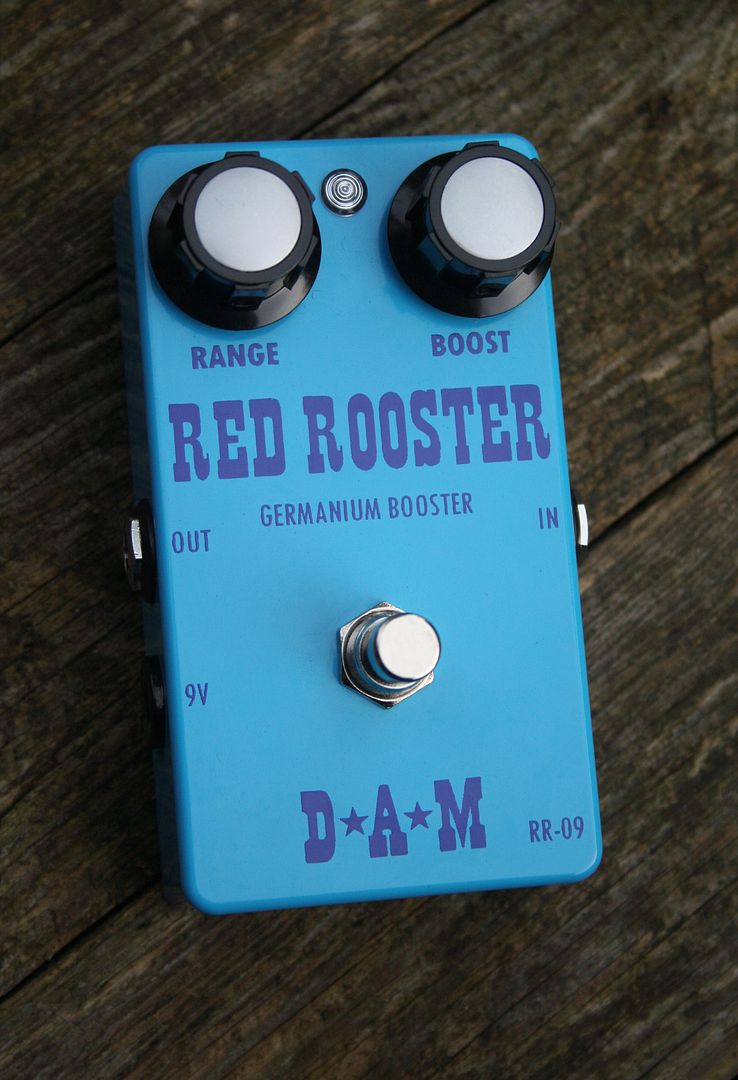
Now, here's what I really want to look at; the D*A*M Red Rooster - It's an updated version of the Dallas Rangemaster:
Here's a description from the D*A*M website:
"Red Rooster - Germanium Booster. Want to drive your valve amplifier into natural overdrive? Create valve overload at low volume settings? Need a treble booster, a bass booster, and a multi purpose full frequency old school flavoured solo booster? Biggty Bam! Check out the D*A*M Red Rooster. Does all of the above and some. Works wonders in zinging up muddy sounding fuzz boxes and will make weak or low output guitar pick-ups warmer, more dynamic and fuller bodied. ...
Enter the Red Rooster and its plan:
1. True bypass switching. The Rooster is totally removed from the guitars signal when in bypass mode, it will not bleed through and dull your guitars original tone.
2. Features a 'Range' control so treble, full range and bass boost can be acquired. It also means it is well suited to either single coil or humbucking pick-ups of varying output and gain levels.
3. Uses a specially selected and tested high grade Mullard germanium transistor. Usually an OC71 or an OC45.
4. Adjustable biasing so that the germanium transistor is correctly set up to produce a bold, clear dynamic tone with a good amount of sustain.
5. Low noise circuitry using high grade Ero Vishay film capacitors, BC components Electrolytic capacitors and 1% tolerance metal film resistors.
6. A heavy duty cast aluminium enclosure finished in a highly durable powder coated paint job.
7. High quality passive components such as audio grade Omeg potentiometers, Daka-Ware control knobs and Neutrik jack sockets."
And a little demo video:
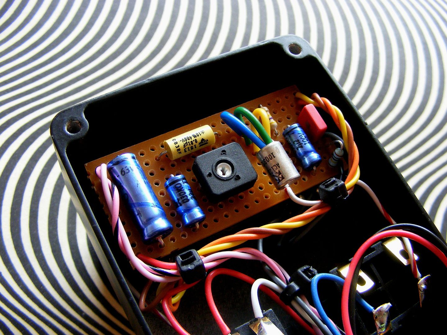
They do sound great and the build quality is second to none, check out this gut shot, neat as you like:
So here's a replica of that layout:
The Boost pot is 10KB and the Range pot is 100KB, the trim pot can be 5K or 10k and you use this to dial in the transistor bias (6.66v on the transistor collector - tune it to the number of the Beast...). You'll need an NPN germanium transistor with a Hfe ~ 100ish (select the Hfe to taste - higher = more grit!)
The Keeley Katana has been a popular boost pedal since it was introduced. It's circuit topology is simple yet it manages to produce everything from a small boost to add a bit of life to leads right through being able to smash the front of a tube amp into submission and natural break up. Here's the description from the Keeley website:
"As far as guitar clean boosts go, the Katana is KING TONE. It's the pedal to have for the finishing touch on your tone.
Want a mirror image of your tone, only louder? This is it. The Katana is also a fat, harmonically rich boost, just pull out on the volume knob and stretch your imagination with overdriven tone! You can keep it on all the time to push your amp harder, or as an occasional boost to cut through the mix.
Obsessed or Compelled with the Fattest, Fullest Drive? Well, Before other people started using Blue LED's and non-diode clipping stages, there was the TMB and Katana.... Cascading FET stages do the tube-amp-thing like nothing else!"
The dual cascaded Jfet stages do sound good, the charge pump ups the voltage to 18v and gives the circuit double the gain of a similar circuit running at 9v. It does introduce it's own clipping when the 10uF cap is switched into bypass the source resistor on the first stage, I prefer the tone without the cap switched in, a possible mod would be to use a smaller cap here to introduce some treble/mid boost to the tone. I also suggest changing the 4k7 resistors for 10k trim pots to allow you to tune each jfet to it's optimal bia's point around about 1/2 V (9v in this case). Build one up, they sound pretty decent for such an easy build!
These things are RARE. It's a Lovepedal Delux 60 Mosfet - they were also sold in a dual format known as the "Twin 60". Greg from the Freestompboxes.org forum bought one and opened it up - here's what he found:
He drew up a quick schematic too and kindly gave me permission to use it (Cheers Greg!):
Don't even ask me what that 47k resistor is doing in parallel to the 100k volume control - I know, it makes no sense. I'll quote Greg on this one:
"An observation. I think Sean has tried to set the .1uF - 47K High Pass filter on the output of the Mosfet so that it keeps guitar frequencies intact. Theoretically it would be 34Hz. But, considering the Volume pot is in parallel with the 47K the filter is actually set higher than he probably intended."
Maybe he did mean it? He also goes on to make the point that if you connected the Karl fuzz directly after this the high pass filter would jump to 370Hz (Due to the 5k pot on the Karl's input..). Hmmm, probably not great!
The Xotic EP Booster has been causing a fuss for a while now. Supposedly based around the legendary Echoplex EP-3 preamp it's been recognised as one of the best boosters currently available.
"What do the tones of renowned guitarist such as Page, EVH and Johnson have in common? They all used the legendary echo machine EP-3 as a pre-amp.We've captured that magic in a new Xotic Effects pedal, the EP Booster.
We've used the highest quality parts available with a discrete FET design and low impedance output, the EP Booster provides up to +20dB of unadulterated boost with multi-dimensional, shimmering highs and lows, and no ear fatigue. The internal DIP switches let you choose the boost frequencies, and EQ settings.
Housed in a small 3.5"x 1.5" x 1.5" case with blue LED and transparent knob, the EP Booster can be powered by 9-volt up to 18-volts.
A simple pure boost that pays reverence to the magical EP-3 and captures the celebrated tones of the world's most famous players.
The EP-Booster,great tone starts here!"
And, of course, a ProGuitarShop demo video for you:
Well, the freestompboxes crowd whipped one apart and took a look inside (Thanks to Greg for the initial tracing):
The original transistors are supposedly 2N5457 and 2SC1815. As you can see it doesn't greatly resemble the EchoPlex EP-3 preamp:
I would make a few modifications to this - firstly it's got to run on 18volts! Then I'd replace the drain resistor with a 25k trim so you could dial in a sweet spot of your choosing. For extra control I would swap out that low pass filter for a version of Mark Hammer's "Stupidly Wonderful Tone Control", that would give you a real handle over your top end. Finally - what's with that nasty BJT transistor output buffer? I'd use a Jfet or Mosfet follower - better fidelity and clipping characteristics!
Anyhow, I might draw a schematic up!
[EDIT] - I told you I'd draw a schematic up, here's the business:
As you can see I've added a master volume control, a tone control (treble roll off) - you could call this control "Sparkle" for added mojo. I replaced the nasty BJT transistor voltage follower with a nice JFET type. I ommited the "bass boost" switch, I didn't like it, it muddied up the boost, you could add it back in if you want. I also included a quick schematic for a voltage doubler to allow you to power this circuit at 18v (where it sounds best) with a single 9v battery. Well, what you waiting for? Go build one :-)
[EDIT2] - If you want to actually reduce the low end present in the circuit I'd reduce the input cap to 33nF and change the bypass cap on the "Boost" control to 220nF ~ 470nF ~ 1uF depending on your preference. I'd also recommend one other small change - replace the drain resistor on the first FET with a 10k trim pot then use it to dial in a 5.5v bias on the Jfet's drain to make sure you've got it in the "sweet spot". Just thought I'd add that ;-)
[EDIT3] - One last thing, for those interested in booster circuits which add colouration to your tone check this out (schematic below), it's a prototype I was working on back in 2009! The values in the treble control need tweaking to find the best response but it sounds pretty good "as is". This thing also sounds best at 18 volts :-) Build it up and tell me what you think:
[Note - This post also contains info on the Landgraff Clean Boost]
I didn't realise I hadn't put up a post for the Zvex Super Hard On - it's one of my favourite little circuits. It's a great booster and also a really good building block when you're designing circuits...
Here's the description from the Zvex website: "This is the perfect preamp pedal. The "Crackle Okay" volume knob is a negative-feedback control styled after classic 60's recording console inputs. (They crackled when adjusted too.) Most vintage guitars suffer from steadily deteriorating magnets in their pickups, since permanent magnets aren't really forever. The Super Hard-On's input impedance is so high (>5 Meg) that it refuses any current flow from your pickup... maintaining the most magnetic field around each string, so you can hear exactly what your pickup sounded like the day it came off the winder. The ouput level can exceed 8 volts peak, and when it finally distorts, the wave is shaped like triode overload, not fuzz."
And the standard demo video of the Super Hard On in action:
Now there are several schematics available for the Zvex Super Hard On as it's circuit has changed slightly over time. The schematic I use is this one (It's the MKII):
[As you can see the zener diode is positioned slightly differently here - it doesn't make a difference to the tone!]
Estragon from the Freestompboxes forum helped to clean up the understanding of the Super Hard On circuit a little with this great post:
"The SHO is a deceivingly simple circuit. There is a lot going on when the source/bias pot is adjusted. First, as the bias pot is adjusted from max (5k) down to min (0 ohms), the DC drain voltage changes roughly from 7.2V down to 4.0V. I have measured this in the breadboard and verified it in the sim (using a BS170 Spice model by Zetex).
Second, the gain varies from 0 dB to almost 40 dB as the bias pot is adjusted. Notice how the variation of the DC drain voltage tends to keep the dynamic range nearly centered. At min gain, drain and source resistors are 5k and 5k, respectively, thus the output can vary from about 4.5V up to 9V, and the 7.2V bias voltage is nearly centered. At max gain the output can vary from about 0V up to 9V, so the 4.0V bias voltage is again close to the theoretical center of the dynamic range.
Third, the input impedance of the SHO is not 5 Mohm as the popular belief dictates. No, it varies big time with the bias pot. At min gain, the end of the upper 10Meg resistor is tied to an inverted copy of the input voltage, not ground, so overall input impedance actually becomes 3.3Mohm when you do the proper math to find out the equivalent thevenin resistor (this has been verified in the sim as well). As the bias pot is reduced and gain increases, something very convenient happens: the input impedance starts going down, down to 140 kohms at max gain. This certainly helps taming the high frequency resonance of any guitar pickup (around 2-5kHz), thus taming highs and helping to the musicality of the clipping. Again, this is because the upper 10Meg resistor is effectively tied to a voltage source that is an amplified version of the input voltage, and not a simple ground point."
There are also other projects available based around the Super Hard On topology. Soulsonic's "Crackle Not Ok" (A Super Hard On without the crackling gain pot":
And Rick Holt's (a.k.a FrequencyCentral) Super Heated Super Hard On (Which changes the circuit from standard Mosfet booster into a Mu-amp mini-booster. *Warning - this thing is seriously loud!*):
Oh, and one more thing - here's the schematic for the Landgraff Clean Boost (Drawn by Clay Jones):
I've had quite a few email's requesting information on this old Lovepedal design that's supposed to emulate that classic "Fender on 6" tone. Well, I've got a schematic for you. First here's the description from the Lovepedal website:
"Reminiscent of the mid 60's Blackface Fender era. Specifically a Blackface Super on 6.
Plug the Super 6 in to a ANY clean amp to nail that mid-60's American amp tone. This unit will turn a small amp into a much larger sounding amp instantly.
With an onboard vintage tone stack to die for, you now have ULTIMATE control over ANY guitar / amp / effects combination.."
And a demo video:
The schematic was originally drawn up by reveriesof on the freestompboxes forum, I've redrawn it for you for ease of understanding:
[NOTE - the input cap should be 100nF, the output cap should be 10nF, this is also true for the 100n cap that bypasses the tone control - it should also be 10n]
With a note to the corrections - I like the pedal with a few little alterations; instead of the 510R resistor I like a 390R which gives you a little extra gain, I like a lower value input cap (22n instead of 100n) and a larger value output cap [the cap that comes before the tonestack right off the 3k3 resistor] (100n instead of 10n). It's a really simple circuit which is great for modifying - get some different value caps and go wild - you'll find something you like.
As you can see it's a deviation from the standard Lovepedal formula of "modified Electra/LPB booster". That BS170 is a mosfet device and they have nice clipping characteristics of their own without requiring any clipping diodes. The "vintage tonestack" is just low pass/mid boost cut type control.
Here's a great little PCB layout(Showing full of board wiring as well) produced by Sinner on the Freestompboxes forum - Cheers Sinner!
Here's the original freestompboxes forum thread for your viewing:
I've decided to make a complete set of the Mad Professor designs that have been traced out. I'm a massive fan of Bjorn's designs and always enjoy seeing all the little tricks he puts into each of his pedals. Here is the "Ruby Red Booster" traced over at freestompboxes.org; http://freestompboxes.org/viewtopic.php?f=7&t=13106 . WhiteKeyHole takes the credit for the schematic :
"The two boosters are based on the much sought after BJF Little Red Trebler and Red Rooster Booster, connected in that order and with a master volume control.
The RRB can be used as a treble booster, a clean boost or an overdrive unit or any combination of the above. Inside the pedal there is a switch for a high quality buffer. You can set the pedal for true bypass mode or "buffer on" in bypass mode. The Treble Booster is a fine-tuned booster for just the right treble frequency with carefully designed bandwidth and an optimized slope of bass cut."
So you got a BJF Little Red Trebler and Red Rooster in there!
Here is a ProGuitarShop demo of the pedal in action;
Yep. It's here alright, I actually drew the schematic up on this one! -
Check it out. Note that the power supply in the scheme is not the original switching type as used in the nano. It'll make no difference to the sound, all the power supply needs to do it provide 230VDC to those plates! You could sub in the power supply from this amp here: http://jjs.at/electronic/class_a_subminiature.html
Demo video:
This was kindly provided by a freestompboxes.org member, many thinks :-)