Welcome to the Revolution

Hi there, welcome to my blog - La Revolution Deux. It's an odd name - but I like it! Here you will find all the info on my various DIY Guitar effects builds, amplifiers and guitars. Everything from a humble Ibanez tubescreamer to the holiest KLON Overdrive.

You may also find a few effects builds that I am looking to move on - usually in exchange for other effects/gear/cash. You can always check my ebay account to see what I've got up for grabs.

Have fun, enjoy the blog - Fred Briggs :-)

CONTACT ME


Feel free to get in contact with me about anything you see on this blog or with any general questions about guitars, amplifiers and effects, I'll be happy to answer! Just click the button above to email me directly or alternately my email address is fredbriggs2007 [at] googlemail [dot] com

Search This Blog

Saturday 30 June 2012

Diamond - Compressor

[This post contains information on the Diamond Compressor & Fred Briggs Diamante]

Diamond make some real high-end stuff; the Memory Lane Delay, Halo Chorus and J-Drive are all top level (expensive!) pedals. My overall choice from the Diamond pedal range is the Diamond Compressor though. It gives a nice compression effect, not the super transparent kind, you can feel the squish but it's not over powering and the "tilt" EQ is a nice addition too allowing you to gently shape your overall tone. Ok, so it's a great sounding compressor and has loads of great features, but my favourite bit; the LED that changes colour with the compression level! Ha.

Here's a description from the Diamond website;

"Recording studios often use rackmount 'vocal channels' - a mic preamp, compressor, and EQ all in one unit as a front end for vocal recording.
The Diamond Compressor is our take on a 'guitar channel' - a dynamics and tone shaping tool for live and studio use - with low-noise, ultra-linear signal buffering, smooth opto-based compression, and a versatile 'tilt' EQ that musically shifts overall frequency balance. All in a user-friendly 3-control package - just Comp, EQ and Volume.

Features:

- Vactrol opto-isolator variable resistance path as used in high-end studio compressors for smooth attack and decay characteristics while preserving initial signal transients.


- Premium audio components, including 2% polypropylene capacitors,1% metal film resistors and a pro audio grade  opamp (our signal path opamp alone costs 8 to 10 times
what the industry norm uses).

- Post-compressor 'tilt' EQ provides a very musical tailoring of frequency response - seamlessly transition from a darker jazz voicing to a brighter jangle, with flat frequency response at the center detent position.
- Double filtering stage in side chain to eliminate low frequency modulation while preserving fast compression response.
- Dual AC capacitive coupling paths for improved transient response.

- Bi-color LED provides visual indication of depth of compression.


- True bypass signal path.


- Battery or standard negative tip 9V DC adapter operation, can be powered from 9 to 24 V negative tip."


Here's the ProGuitarShop video;


Now here's a gutshot (also from the Diamond website);


And, thanks to some incredible work by WhiteKeyHole, a schematic;


So, interesting parts of the design - the Tilt EQ is taken from an early 70s stereo preamp designed by Quad Ltd, it gently tilts the eq around 900Hz simultaneously boosting treble and cutting bass and vice versa (mid position is a flat response). It's a great tool for smoothing out EQ ranges and matching various pedals up to one another without sounding too drastic and overpowering other pedal's tonal characteristics. Another addition not normally seen in stompbox design is the current source that has been added to the emitter follower buffer stages. The addition of the current source to these stages reduces the THD (Total Harmonic Distortion) from 0.01% to 0.001% - not something you're really going to hear in a guitar orientated world! Those paralleled capacitors too - not really necessary!

Here's a closer look at the Tilt control schematic;

And a graph of the EQ response curve (note the phase inversion of the signal at extreme settings of the control);


After looking at the Tilt EQ schematic you'll notice that the bypass resistors R13 & R14 have been left in the Diamond design even though they are not needed, you could in fact remove them and not notice a difference.

Parts List;

Capacitors 
NOTE - C33 on the schematic is C32 on this parts list.
Caps 2u2 and higher are electrolytic. C22/23/30/31/32 are ceramic, all other film
C1 47u
C2 47u
C3 47u
C4 5n6
C5 5n6
C6 330n
C7 100n
C8 100n
C9 100p
C10 820p
C11 100p
C12 820p
C13 1u
C14 100p
C15 330n
C16 820p
C17 820p
C18 100n
C19 10n
C20 10n
C21 2u2
C22 100n
C23 100n
C24 820p
C25 3n3
C26 15n
C27 10n
C28 4u7
C29 3n3
C30 100n
C31 100n
C32 100n

Resistors
All metal film 1% except R1 which is carbon film 5%
R1 100R
R2 10K
R3 10K
R4 100R
R5 15K
R6 3.32K
R7 22.1K
R9 15K
R10 47.5K
R11 47.5K
R12 47.5K
R13 47.5K
R15 1M
R16 475R
R17 475K
R18 475K
R19 3.32K
R20 6.41K
R22 100R
R23 475K
R24 22.1K
R25 100K
R26 1K
R27 3.32K
R28 475R
R29 221K
R30 475K
R31 100K
R32 221K
R33 100K
R34 475K
R35 221K
R36 10K
R37 1.5K
R38 10K
R39 Jumper
R40 10K


Transistors are standard NPN/PNP medium gain
LED is a Tri-colour type.


For those after a layout to build this thing check out Harald Sabro's great layout here; http://www.sabrotone.com/?attachment_id=2157

Here's the freestompboxes.org forum topic; http://freestompboxes.org/viewtopic.php?f=7&t=850

Now, I previously mentioned that the Diamond has many superfluous parts and circuit structures so I decided to simplify it right down. Here's what I came up with;


Basically it's the same circuit as the Diamond just as simple as it can be; the buffers have been removed or simplified and the EQ section has been removed completely leaving controls only for "Compression" and "Volume".

Thursday 28 June 2012

Devi Ever - Console Kickstarter!?


Remember your old Nintendos and SEGAs? Well this is a rebirth of the old "cartridge" based systems but this time it won't be Super Mario you'll be booting up - it'll be some killer fuzz tones. Devi's been working on this one for some time so if you're intrested get over to the kickstarter page and get involved; http://www.kickstarter.com/projects/deviever/console-ii-cartridge-based-multi-fx-guitar-pedal

Tuesday 26 June 2012

Rothwell - Love Squeeze Compressor


"Designed and Built in Britain"; the mark of quality and the Rothwell Love Squeeze doesn't disappoint - it's a great hand built compressor pedal with an interesting design.

Here's the description from the Rothwell website;

"The Love Squeeze is a compressor designed simply to sound right with guitars, without any bizarre “pumping” effects and without any noise.

This has been achieved by designing a circuit from scratch instead of adopting the more common approach of using an operational transconductance amplifier (for tech heads, it’s usually the CA3080 chip) or simply copying an existing design (like some American boutique makers have done) and gives the Love Squeeze a sound of its own. Low level signals can be raised by as much as 20dB without boosting high level signals, so when used in front of distortion - either in a pedal or an amp - leads lines can be fattened up without chords sending the distortion into mush.

When used with a clean sound the Love Squeeze can be set to just take off the ice-pick attack of single coil pickups for a tone a little easier on the ear. Like reverb (when used sensibly), this is a subtle effect which can go almost unnoticed until it is switched off - then you wonder how you could live without it."

Here's the ProGuitarShop demo of the Rothwell Love Squeeze in action;


And another (with the Rothwell and Keeley Compressor);


Now, check out some gut shots - notice the high quality PCBs, neat wiring and general high standard of construction throughout :-) An all round decent piece of work!


Here's a schematic drawn up by ever productive WhiteKeyHole;


It's an interesting concept and a nice simple design. The use of a FET as a voltage controlled resistor makes the attack nice and quick and cuts out the cost of an expensive LDR. If I were to compare the tone of this thing to anything else out there it would be the old traditional Orange Squeezer - it's subtle and transparent compression, it doesn't pump and breath a'la OTA designs or higher ratio optical compressors. Overall I'd say it's a very nice little "tone tidier" compressor.

For those who want to build this thing here's a vero layout from the fantastic Harald Sabro; http://www.sabrotone.com/wp-content/uploads/2011/09/LoveSqueeze.gif

Sunday 24 June 2012

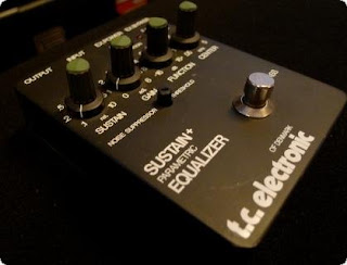
TC Electronics - Sustain + Parametric Equalizer


This is a strange one, a super rare beast, but I had the opportunity to play with one the other day. The controls are a little tweaky and it's also sensitive to the position it's placed in the signal chain but when you get it right! Wooo, there's some great tones here; super long sustain and really punchy rhythm tones and with the parametric EQ you can really pick out certain frequencies that you want to accentuate or remove.

Personally the compression/sustain/noise gate part of this pedal is the one that I like, the parametric eq can be covered by other pedals but the sustain/noise gate section really is something unique. Flicking the distortion switch on gives you some nice clipped tones that add a nice smoothness to your tone.

There is very little info around the internet for these things and even TC Electronics struggle to provide info. I did discover that David Gilmour used a couple in his rig in the late 1980s though; http://www.gilmourish.com/?page_id=2111

Ok, so here's the description from the TC Electronics website (This description was in place for the reissue version that is also now discontinued!);

"One of the true grails of vintage effects pedals. This one really enhances your tone. Go from subtle compression to extreme sustaining effects at the tweak of a knob. This sustainer will prolong life of even your weakest tone otherwise destined for premature death.

The Classic Sustainer + Parametric EQ gives you studio quality compression in a pedal. Crank it to the extreme and it’ll give your sound that percussive “thud” brilliant for funk or country. And with its parametric EQ you’re in full control of which frequencies to target."


After even more searching I uncovered some gutshots of the pedal, check out the goofy 1980s PCB design;


After some more exhaustive searching and a trip to the WayBackMachine I discovered this;


Yes! A schematic file for the pedal. I'm going to have to study this one for a while until I really understand what is actually going on fully in the noise gate/compression section of the pedal but it's a pretty interesting design incorporating both OTAs *and* op amps in various feedback loop configurations. I'm probably going to have a play around with this design and see if I can distil the compression section into a little project for people to build up.

Friday 22 June 2012

Fender Tweed "Deluxe" - Model 5E3


The Fender Tweed Deluxe has been with us for over 60 years now and it's popularity is still growing. First produced in 1948 as the Model 5B3 it is the mid 50s 5E3 circuit that guitar player claim is the greatest revision of the classic Tweed formula. 

Originally viewed as an "entry level" model the Tweed Deluxe has become one of the most recorded and iconic guitar amps of all time. It's sweet breakup and touch sensitive nature really allow the guitarist to feel like they are truly in control of the circuitry with every tone required available from slight alterations in pick attack or the guitar volume control.

If, somehow, you've never heard a Fender Tweed in action here's a demo video;


And another of a clone in action;


So, let's have a look at the schematic;


Super simple for a push-pull amp. All there is is two cascaded preamp stages a super simple "Cathodyne" phase inverter and a cathode biased push-pull power stage. The power supply is pretty poorly regulated and combined with the valve rectification isn't exactly what amp designers would call "Stiff". It's this simplicity combined with an errant luck of design that make the 5E3 the legendary amp it is. Below is the original layout as used in the actual amps themselves;


And here's the Ceriatone layout (based on the original layout but a bit easier to read;


For a full project pdf file with schematics and layout files (and a few mods!) check this out;


Here's a great site with loads of discussion on Tweed builds/mods and tones. There's some great demos too; http://www.recproaudio.com/diy_pro_audio/tweed_deluxe.htm

Wednesday 20 June 2012

Voltage Scaling in Amplifiers - Power Scaling / VVR

Dana Hall's VVR3 PCB kit.
Power Scaling (a London Power trademark) and VVR, which stands for Variable Voltage Regulator, (Dana Hall of Hall Amplification's version of Power Scaling) are currently two of the hottest topic's in the Guitar Amp world. Both are methods which allow you to scale back the voltages within your amplifier to attenuate the overall volume without having to use a cumbersome purpose built attenuator between the amplifier's output transformer and speaker or rely on a simple "Master Volume" control which dials out the all important power tube clipping.

Voltage scaling is said to allow you to maintain "that" tone you get from running a tube amp flat out with all the volume controls turned up to the max but also allow you to maintain your relationships with neighbours/children and/or spouses without having to resort to playing your guitar in an underground bunker.

Best of all this technology is compatible with 99% of amps below 50W!

Firstly; SAFETY! If you're not confident working with the voltages associated with tube amplifiers don't even bother with this, you WILL end up toast.

Secondly; what is "Power Scaling" e.t.c, why use it and how does it work? Well, take these explanations from the London Power website;

"[Power Scaling's] goal is to achieve the same tone as our loud sound but at a much lower volume."


And;

"Power Scaling, when implemented correctly, will reduce amplifier loudness by reducing the power generated. This has the added benefit of extending tube life while retaining "cranked" amp tone at any loudness level. Power Scaling can be applied to any tube amplifier, regardless of bias method or push-pull versus single-ended."
You may just wonder why not use an attenuator? Well, London Power has this to say regarding attenuators (and remember there *may* be a slight bias in their explanations!);

"Not at all! "Speaker load boxes", "speaker emulators," and "speaker attenuators" are all forms of attenuation that are interposed between the output of a power amp and the speaker. They work for some people but are notorious for sounding "buzzy" at high attenuations.
A speaker attenuator forces your amp to be run flat out, producing its full power all the time. The power that is not needed is thrown away as heat, with the required power going to the speaker. It is quieter than full-tilt, but now the speaker is isolated from the amp and cannot interact with it, so some tone is lost."

What about a standard Master Volume control?;

" If you only play clean or you only use preamp overdrive or distortion tones, then a 'master volume' will satisfy you. 

Power Scaling is the best solution for those players who incorporate some amount of output stage "effect" in their sound. This effect can be some clipping, heavy clipping, or just that cusp of compression you get in a tube power amp approaching clipping. Power Scaling allows you to live at that cusp or beyond, but at ANY loudness you need."

So how does it work? Here's some info from Dana Hall;

"It makes the B+ on your amp variable like using an external variac only unlike the variac it doesn't affect your heater voltage. As you turn down the voltage on your tubes you drop the power but keep a lot of the characteristic distortion and sustain only at a lower volume.

It reduces the output of the preamp IF you regulate the whole amp VS just the power tube(S). Since the power tubes are also operating at reduced voltage, they are actually easier to saturate. If you regulate just the power section and keep the voltages normal on your preamp tubes then you will need a MV to keep the preamp from over driving your power tubes. If you regulate the whole amp the preamps voltage is also reduced and the gain structure between the preamp and power amp is maintained."

So, to sum up VVR, Power or Voltage Scaling, whatever you want to call it, is just one way of getting those great amp tones at lower volumes. Using some simple circuitry to regulate, and lower upon demand, your amp's power supply it enables your amp to go full bore but at acceptable volumes.

Here's a demo of a Dr Z Route 66 with Hall Amplification's VVR3 installed;


And another VVR equipped amp;


Now, for a huge amount of information regarding VVR check out this pdf document written by Dana Hall. It includes *almost* everything you would need to know about voltage scaling amplifiers including how you select the right VVR circuit for your amp (be it cathode or fixed biased), what parts of your amp you should scale (preamp, phase inverter, power amp) and how to install VVR in your amp;


Now here's what a Valve Junior circuit looks like with a VVR circuit installed to regulate the whole amp;


Here's a schematic of the VVR schematic and PCB layout for cathode biased amps (for more info on amp bias types check out the VVR pdf above);


And here's a (fairly crazy) video explaining how to install a VVR unit in a cathode biased amp;


So if you fancy a try at VVR here you go, build up the circuit and install it in your amp! I'll draw up some schematics for the Fixed Biased voltage scaling unit in time and present them here.

Fred Briggs - Pharmacy Fuzz


Here's something I've never seen before in a Fuzz Face type circuit; adjustable gain darlington pair transistors made up of individual germanium and silicon transistors. The first transistor of each pair is a germanium device of around 50hfe (low leakage!) and the second is a silicon device of around 250hfe. The adjustable nature of the transistors makes the Pharmacy Fuzz capable of a huge array of both vintage and modern fuzz tones - you can tweak and play with the circuit for hours and still find new possibilities.

When I build this up I'll be using a 100k trim for the gain control on the first transistor set and a 100k pot for the control on the second transistor set as this secondary pair is where most of the clipping magic happens (or indeed just use a single low/medium gain transistor instead of the first pair for simplicity). Also note the "Aggression" and "Bass Cut" controls. The "Aggression" control works as a circuit wide "overall gain" control and allows the circuit to go from mellow to full on rock out. The "Bass Cut" is just an implementation of the now pretty standard Fuzz Face tone blend control and governs the amount of low end signal that the circuit will gobble up at it's front and and fuzz out at it's end.

The 10k trim is there for bias - use this to set the voltage on the collector of the second transistor set to around half the supply voltage, or to wherever you think it sounds best!

You'll also note a few other little inclusions in the design - the 2 x Ferrite Bead inductors in series with the input of the circuit and the Suppression Choke in the power supply (whose overall resistance should be in the 50-100 ohm) region. These components together help to reduce noise and radio interference in the circuit. If you don't have them replace the suppression choke with a 100 ohm resistor and just omit the ferrite beads.

Tuesday 19 June 2012

Divided By Thirteen - CJ 11 Amplifier

Divided By Thirteen CJ 11 in Cream
Divided By Thirteen are a relatively new company (with regards to amp manufacturing) based in California and spear headed by Fred Taccone. They make some great sounding and beautifully build amps, not to mention the way they look!

The CJ11 is one of Divided By Thirteen's smaller offerings and provides all the "overdriven Fender" goodness you could possibly need.

Here's the description from the Divided By Thirteen website;

"When asked, by Corky James, amongest others, "Can you take my favorite 1959 tweed amp from Fullerton and instead of the controls being Volume Volume Tone make it Volume Treble Bass, give it more clean headroom, a wider range of usable overdrive (throw in a little EL 34), make it a little louder with fuller, tighter low end, and put a master volume in it so i can play at all levels and dial in and hit the sweet spot of whatever speaker i am using at the time, mostly a G12M Celestion?"

Sure.

Powered by 2 6V6GTs it's hard to believe the performance of this stout, 11 watt, 1x12 combo that is just the latest in an ongoing tradition here at Divided by 13 of collaborating with and responding to what players, writters, and produceres ask us to do."

Did I mention Divided By Thirteen make some beautiful amps? Check out the SJT 10/20 below, I'd love one of these;

Divided By Thirteen SJT 10/20
But back to the CJ 11 - we all want to know how it sounds, so here's the trusty ProGuitarShop video for you;


Let's have a look at some gutshots of this beauty;


As you can see the top notch worksmanship isn't just limited to the cabinets and finish it all continues on the inside. High quality parts throughout and clean concise wiring - the perfect way to make a great sounding tube amp.

Here's the schematic that has been deduced from all the available photos;

Below are the two schematics for the Fender Blackface Deluxe AB763 and the Fender Tweed Deluxe 5E3 circuit. You'll notice that the Divided By Thirteen CJ11 is basically a tweaked composite of these two classic Fender Deluxe designs - the AB763 preamp and the 5E3 Phase Inverter and Power Section;


The 3k3 cathode resistors bias the preamp stages quite "cold" meaning a slightly brighter and glassy tone is produced which really emphasises the CJ11's Fender roots.

Pigtronix - Philosophers Tone Compressor (Germanium Gold)


I love compressors. I love them more than any other guitar effect - and there's a reason; they are the glue that sticks a great performance together. Unless you're Jimi Hendrix or Eric Clapton a compressor *will* improve your tone and help you sit in a band mix much better.

The Pigtronix Philosophers Tone has been making waves for a while now and I thought it was time to get it placed up on the blog.

Here's the description from the Pigtronix website regarding the regular version of the Philosophers Tone;

"The Pigtronix Philosopher’s Tone is a state-of-the-art analog compressor / sustainer, providing endless clean sustain. With variable Sustain, Blend and Treble controls, the Philosopher’s Tone offers a huge range of compression sounds for the discerning musician. The Philosopher’s Tone also contains a harmonic distortion for clean or dirty compression sounds and any mixture of the two. While the Philosopher’s Tone rocks on its own, it is designed to play well with other dirt pedals in order to create your ultimate distortion tone that sustains forever.

Pigtronix Philosopher’s Tone is unlike the common compressor. This pedal has more sustain and less noise. The dynamic range, touch sensitivity, overall transparency and outright sustain of the Philosopher’s Tone is un-paralleled in the crowded world of compressor pedals.

Practitioners of the mystical and ancient art of alchemy long sought an element called the Philosopher’s Stone, believing that, if found, it could turn lead into gold and bestow immortality upon the man who wielded it. For such a tiny pedal to create so much sustain, this device represents a musical equivalent to this mythical substance in the world of guitar pedals."


And to get an idea of how the Philosophers Tone sounds here's the ProGuitarShop demo video for you;


Now, onto the guts of this thing. Thanks for these photos goes to jwpartain1 of the freestompboxes.org forum;


From these gutshots and the attached information Mystic Whiskey managed to draw up a schematic and verify a build against an original Philosophers Tone Gold Germanium. Here's the scheme for you;


Let's have a look at a few of the different sections - the "Grit" control blends in either a clipped or clean version of the compressed signal. The "Blend" control blends between the unaffected signal and the compressed/clipped signal. The "Treble" control is nothing special and is set up as a simple treble cut. It's a decent design and really works for a nice overdriven yet compressed tone.

For those of you brave enough to take it on - here's a vero layout for the Philosophers Tone Gold;


For reference here's the freestompboxes.org forum topic; http://freestompboxes.org/viewtopic.php?f=7&t=11954

Active Pickups? How do EMG do it?


The EMG 81 is now ranked as a "classic" humbucking pickup - for years it has been the go-to choice for Shred and Metal guitarists thanks to it's monstrous voltage output (making it a doddle to overdrive a preamp!) and searingly smooth high frequency response which allows guitarists to cut straight through all the sludge of the bass and drums, and, depending on the band - the singing too ;-)

Here's a description of the EMG 81 from the EMG Website;

"One of the most popular EMG’s the 81 is the one that started a revolution. Utilizing powerful ceramic magnets and close aperture coils, the tone was designed with detailed intensity, incredible amounts of high end cut and fluid sustain. Traditionally used in the bridge position, this pickup will make your leads slice right through even the densest mix. When used in both neck and bridge positions the sound can only be described as blistering."

And a demo of the EMG 81 in action and in comparison with some other EMG actives;


I've got to say - it's not exactly a sound I use very often (ever?!) but active humbuckers can be used in other genres apart from Shred and Metal. As long as you know how they work and how to alter their characteristics anything is possible (well, maybe not an active pickup designed for Country Twang!).

Luckily, someone's taken one of EMG's babies apart and they reckon they've got the whole thing worked out! Firstly here's some general specs on the EMG 81 construction from whoever took them apart;

"Magnet: Ceramic (cutting) 56x3x13mmWire: 0,06mm (Plain Enamel) (#42 AWG)
Core: 54x3x12,5mm (silicon steel?), solid steel.
Coil: 4,18KOhm (one coil), wax potted, aprox. 5700 turns, h=7,5mm
Bobbin: 64x13x9mm (or with "tube legs" 12,2mm)

Coils conection:

-opamp--------^^^^^^^^-----ground----^^^^^^^^^^---------opamp+

IC unknown, marked as EMG001"


And another video of an EMG Factory Tour (with some interesting info on the EMG 81 specs.);


And for the nosey ones here's some images of the gutted EMG 81 humbucker ;

Cover off, wax potted coils and ceramic magnet

The mystery EMG chip (suspected LM4250)
The coils and solid steel blade bobbins
Furthermore the guy who gutted the EMG 81 also traced out the circuitry inside - here's the schematic of the active circuit;

Now the freestompboxes.org forum has had a good look at this and the main proponent to it's development and implementation was the great Bajaman. Here's some of his key posts (edited slightly by myself for clarity);

First up is a post regarding the original schematic;

"Referring to this scheme it is easy to see that it is a classic differential amplifier circuit stage - any noise or hum appearing on both coils gets attenuated in the same ratio as the overall gain. In simple terms we end up with a very quiet and super humbucking pickup, BUT in the EMG81's case there exists a slight imbalance in the differential arms. Although both coils feed via 22n dc isolating coupling capacitors, the coil connected to the non inverting input is missing it's source resistor - in the schematic's case 30k. In practice this will not make much difference if any to the noise cancelling efficiency but it will create some imbalance of signal gain in the higher frequency region where the rising coil inductances come into play."

And some quick info on the LM4250;

"The LM4250 is a programmable current op amp with a specific pin out configuration. You set the operating current (and slew rate) with one external resistor - in this instance a 1M value sets the current draw to 80 uA for a very long battery life."

Here's some info on a pair of active humbuckers he constructed using the EMG plans;

"I wound two of the Stewart McDonald alnico humbucking pickups last week and attached two EMG style differential preamps on the bottom nickle silver base of each pickup. I soldered the through hole components on the copper track side of the PCB, then filed the leads flush with the plain side of the board. I inserted a small sheet of mylar overhead transparency film between the board and the baseplate to avoid shorting anything to ground. I soldered the earth bus at each end of the PCB to the baseplate of the pickup and ran a small bead of glue to hold it firmly in place. I laid the film caps and the electrolytic on their sides to keep as low a profile as possible and to assist soldering to the PCB.I wound around 8000 turns of 42 gauge enamelled copper wire (.050) on each bobbin and connected the start of each coil to the metal baseplate. 

The finish of each coil winding was fed to the non inverting and inverting inputs of my active preamp boards.

I wanted to retain the sound of a high output side by side humbucker, so I used a resistor in series with the non inverting input, unlike the EMG 81 which has no resistor fitted and consequently has a more single coil resonance. I used larger biasing resistors (330k each) unlike the 170k resistors fitted to the EMG 81, because i did not want to damp the resonance and shift it's frequency too far down - i suppose I could have used 1M resistors for an even brighter and higher resonance, but in practice the pickups sound very nice. I tried them out with my band mates at practice in the weekend and they were most impressed with the lack of noise and the smooth sound I was getting without any pedals.

It should be possible to fit the active preamp boards to most un-encapsulated humbucking pickups. All that is required is to separate the wire connecting the two coils in series and bring each coil winding out to the non inverting and inverting terminals of the differential preamp board - the existing output is simply grounded by connecting it to the baseplate."

One of Bajaman's active humbuckers

PCB Layout for active humbuckers
Here's a post regarding how each component can be altered to affect tone;

"The component values can be altered to tone model your pickup to your taste.I would encourage reducing the 33k in series with the non inverting input - possibly with an external trim pot to dial in the brightness of the pickup - reducing this to zero should give a more single coil like sound perhaps while still retaining the noise cancelling properties of the differential gain stage.

ALSO - the 22n capacitors can be decreased for less bottom end response OR the two 330k resistors can be reduced or increased in value - this will alter the pickups resonance - lower values should lower it's effect and possibly shift the resonst peak down in frequency - higher values (say 2.2M) should give a much more pronounced resonance at a higher frequency for a brighter sounding pickup.
The 1M resistor can be increased for still lower current drain but reduced top end response, or increased for a brighter top end but lower battery life."


And a post detailing some changes he made to his circuitry and the affect these had on the pickup's tone;

"I noticed that the high frequency end of the pickup's response was a bit restricted (perfect for jazz guitar players) but not enough "bite" for my liking. As mentioned in my last post i wound two pickups (4 coils), each coil wound with 8000 turns of .050 wire on Stewart McDonald alnico humbucking pickup kits. Most Gibson pickups used in Les Pauls and 335s etc. use 500k volume pots which load down the coil and tame it's high frequency resonance. If you have ever fitted a humbucker in a Strat style guitar with 250k pots you will know what I am talking about - the resonance and "bite" of the pickup is nowhere near as bright sounding with this lower resistance in parallel damping the coil's response.

Well - i took another look at my differential preamp design - I was using two 330k resistors to bias the non inverting op amp input to 4.5v dc. These resistors are effectively in parallel if one ignores the low impedance of the battery supply - or 165k, which is a very low resistance in parallel across the pickup coil, and here is the problem!!

For the differential amplifier to work correctly the feedback resistor from the op amp's output to the inverting input also needs to be this value ( 150k + 15k = 165k).
So how do we load the coils with 500k - simple, we use two 1M resistors as the bias resistors and two 1M resistors in parallel with each other for the feedback resistor. We do get a little more gain from the higher value resistors which is not necessarily a bad thing as it turns out because the sound is now a lot better with an almost identical "bite" to a genuine Gibson high output (not an SG) Les Paul pickup when the volume control is set to 7. The extra output gives a really nice fat response that easily overdrives most clean channels on tube amps etc.

I have A B tested my guitar fitted with this pickup and preamp configuration and another guitar i have fitted with two EMG81 pickups and it makes the 81s sound very thin and lifeless in comparison.
The humbucker "squark" is there in spades with no discernable noise whatsoever - even in front of a computer monitor.

When I turn the guitar volume from 0 to 10, I cannot hear any increase in noise whatsoever, which is eerie to say the least."


For those of you who can't find the LM4250 here's another active pickup circuit designed by Ed Tavares of Handmades from Brazil that uses the TL061;


So, you've got the schematics and the plans - go build yourself some active pickups and rock out! As a final note - people usually ask how to wire these things into their guitars so here's a diagram showing the most basic wiring diagram of an EMG 81 type active humbucker;


Here's the freestompboxes.org forum topic on the EMG 81 for reference; http://freestompboxes.org/viewtopic.php?f=3&t=880

Friday 15 June 2012

Tube Sound OD / Briggs PAF Overdrive

This little circuit is part of DIY pedal designs early beginnings. I first ran into it when I was surfing the early DIY forums in the early 2000s but never really paid it much attention, I wish I had done because it sounds great!

Here's the original newsgroup posting in which Arsenio Novo presents his circuit idea (from the 4th July 1995!);

"********************
From: Arsenio.Novo@mba.org (Arsenio Novo)
Date: 04 Jul 95 23:04:50
Newsgroups: rec.music.makers.guitar
Subject: New Overdrive Circuit
Organization: MtlNet (MBA.org) MBA [514-465-8524] Brossard, QC

Hi,

I've noted that talk on this echo always comes back to the subject of
overdrive distortion. Whether generated by a vacuum tube amplifier or
a transistor amplifier there seems to be undeniable differences to me
as well.

Lately, I was tinkering with an unusual transistor circuit
configuration I had come upon a few years ago and made a few
modifications to the circuit that turned it into one beautiful
screaming "tube-like" overdrive but without the wall of noise these
things usually make. When pushed it even makes that distintive
"zoo-zoo" sound...!!!

The original circuit was simply a complementary matched pair of
transistors connected so that all the terminals overlapped. i.e. both
bases tied together, emitter of the PNP connected to the collector of
the NPN, and the collector of the PNP connected to the emitter of the
NPN. 


This transistor pair is then biased by 2 equal value resistors in each
of the compound legs, one to the positive supply and the other to
ground common. The signal is coupled to the base pair leg and the
output is picked off either of the other 2 legs.

The result is that the above circuit exhibits the behaviour of a
multiplier over a range of signal values. It basically performs a
sin function: in other words a frequency doubler.

This doesn't have a very good distortion sound though because it is
rather "burpy and buzzy". However, lately I was toying with the
circuit when I offhandedly decided to try doing something to it just
to see what would result.

After adding a large cap from the NPN's emitter to ground the thing
went wild on me... WANGO ZE TANGO! SUPREMO DISTORTION! I then
proceeded to refine the circuit a little more and got a better
understanding of what it was doing.

The final schematic follows but first a couple of notes on the
circuit. The "bias balance" trimmer should be adjusted for a
symetrical clipping threshold of the output signal as viewed on a
scope. Short of this it can be easily set by "ear" for the most
sensitivity somewhere around mid-turn.

The input should be driven by a lo-z stage if your electric guitar
doesn't have a built-in pre-amp. You can alter the emitter capacitor
value in a range from 0.1uF to 1uF in order to obtain various basement
characteristics but I found the indicated value is a good compromise.
The input capacitor should not vary much either though because if it
is made too large the circuit goes balistic and cuts out on the tutti.

The operation of the circuit more closely resembles a vacuum tube than
a diode clipper does because of the strong square law characteristic.
This is due to the negative feedback around both base-emitter pairs.
This feedback accentuates the junction non-linear behaviour manyfold.

Thus each transitor drives the other even harder so that the transfer
curve ends up more logarithmic than is typical of a single transistor.
In other words: the clipping is gradual and not abrupt like it is in
the case of a silicon diode. Typically a lot more 2nd harmonic is
produced as well. As a bonus the waveform folds over on itself when
the circuit is overdriven!

Now in the interest of the common good I donate this design to the
public domain for personal use but retain copyright and reserve all
rights for any commercial purpose. In other words build one for you
and your friend but if you have it massed produced for profit I only
ask a fair share.

Please, do try the circuit and leave any comments in private at my
e-mail address: arsenio.novo@mba.org
****************"

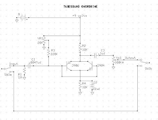
The original message had ASCII artwork depicting the circuit schematic but it was hard to read, here's an image of the schematic instead;

As you can see it's a strange arrangement for the two transistors, something (as far as I can remember) that I've not seen done before or since.

The sound is excellent for such a small parts count and can be described as "COT" like (as in similar to the Lovepedal COT/Electra Overdrive) but I find the clipping to have a much more natural feel and a less drastic on set than the Electra circuit. You can get all those low to medium gain blues tones from the circuit and much more if you play with your guitar volume knob. I especially liked the tone with single coils where the break up felt very natural and dynamic. This circuit certainly does give you something a little different from all those Tubescreamer type controls.

It sounds really good even if you just build it as it is, there are a few modifications that you can make to the circuit to improve the tone even more;

1) The input impedance of the circuit is low and it loads your guitar down - the addition of an input buffer sorts this right out.

2) There's not gain control! Not a massive problem in itself as you can control all the gain you need from your guitar volume pot but some people like a gain control on an overdrive.

3) No tone controls. Again, not a massive problem but it would be nice to have a little control over the top end content.

So, here's the circuit with a few mods and additions;


So there you have it - controls for Bass, Gain, Treble, Boost and Volume. The 20k trim provides bias (I actually used a 50k trim in my build), you can bias by ear - just tweak until it sounds best! In reality I wouldn't build this up with all of those controls. I'd build it with the 2n2 cap subbed for a 33nF with a 33k resistor in series with it and remove the bass control completely. Also I'd bypass the gain control so the circuit is running at full gain all the time. That would leave you with the Boost, Treble and Volume controls - the standard 3 knob overdrive layout (you could even have the boost knob as an internal trim pot). I also had good results subbing in the Big Muff type tone control from the BSIABII (The same control that is in the Zvex Box of Rock) in place of the treble control and omitting the Bass control.

[EDIT] Here's another few mods I'd like to suggest for this little circuit. Basing these mods on the first schematic of the Tube Sound OD;

"The TubeSoundOverdrive is a nice sounding little circuit. There are a few mods I make to this thing when I build them;
1 - I add in a 100kB (Linear) pot wired are a variable resistor in series after the input cap, this allows you to smooth the tone out, reduce the gain a little and take away some of the cutting highs (in some builds where I don't want too many knobs I just use a 10-15k resistor instead of the pot),

2 - I raise the input cap to 22/33nF (depending on how much bass is wanted),

3/4 - I add in a 4n7 cap in parallel to a 500kA (Log) volume pot, this further reduces the overpowering top end,

5 - Instead of using a 10uF bypass cap on the 10k resistor from the NPN transistors emiitor I use a 470nF cap as the bypass, I then wire up a series configuration of a 10uF cap with a 4k7A (Log) pot, this is then wired in parallel to the 470nF bypass cap. This mod allows you to control the overall gain/low end saturation of the build. With this mod you can go from treble boost right through to a full range boost."

If you're sick of tubescreamer type overdrives I'd strongly recommend you give this little circuit a build - you won't be disappointed.