
Pete Cornish doesn't like true bypass: http://petecornish.co.uk/case_against_true_bypass.html
So inside all of his pedals he includes a buffer to aid the switching process and act as a line driver for the remainder of the pedal chain. He sells these individually as the LD-1 (and LD-3 with the mute switch and tuner output).
Here's a description from the Cornish Website:
"Our low noise discrete component Class A pre-amplifier has been specifically designed to overcome the problems often encountered with amplification of Electric Instruments fitted with magnetic transducers.
A frequent cause of these problems is the mismatch of the impedance in the electrical circuit between the pickup and subsequent equipment: this mismatch has been completely eliminated with the introduction of our LD-1™ Line Driver.
The input impedance is identical to a high quality tube amplifier and our Class A Pre-amplifier also features a highly effective RF filter which will help prevent interference from nearby radio transmitters.
The pickup output should be connected directly to the LD-1™ input with a low loss, screened cable; the LD-1™ output can now be fed to any effects or volume pedals (if used) and then on to the amplifier, using fully screened cables throughout.
A further use of the LD-1™ is to isolate long cable feeds which can cause signal and tone losses at the end of an effects chain, particularly if the final effect has a high impedance output (for instance a 250KW foot volume pedal). When using many effects it can be beneficial to add a LD-1™ mid way along the chain thus preventing a build up of signal losses that can occur with mismatched impedances between effects."
Well, someone's taken a few Pete Cornish pedals apart and here's the schematic for the buffer:

And here's a vero layout from IvIark (http://tagboardeffects.blogspot.com):

Hey, could I use bc550 transistor instead of bc549 for this buffer? I've check the data sheet and it looked like the only differences between these two transistors is That bc549 max volt for E and B is 30v, while bc550's E is 50V and B 45V. Would that make any difference for the buffer?
ReplyDeleteIt wouldn't make that much difference, any silicon npn transistor with decent HFE should work..
ReplyDeleteThanks! So what's a good range for decent HFE?
DeleteWell the BC549 and 550 will have hfe's around 500ish...
DeleteCool thanks. I've also noticed that all your replies to comment ends with multiple dots...
Deletelol haha but yeah, thanks for replying. Love this site!
HEhhh, I'm a dot addict! Glad you like the site :-) ...
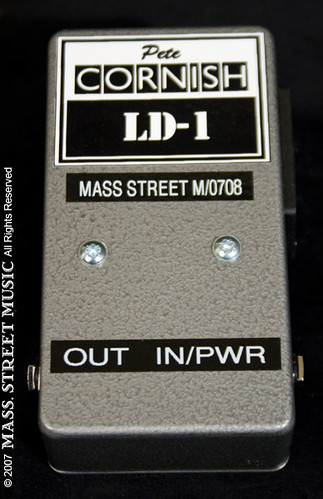
DeleteWow! You will not BELIEVE how much the LD-1 goes for - $399!
ReplyDeletehttp://www.massstreetmusic.com/store/show_item/2364
For a single transistor emitter follower circuit! Holy cow!
Hi Fred, very cool buffer layout! Just a question: do you use a 3pdt switch wiring? If not, what's correct wiring to use?
ReplyDeleteThanks!
Works pretty well! It adds a bit of top end back to my bass.
ReplyDeleteJust wondering why there is a Diode in the Veroboard layout but not in the schematic. Unless I missed it somewhere.
ReplyDeletePolarity protection.
ReplyDeleteThis buffer is very different from what is illustrated in the Mad Bean G2 schematic. r1: 10M vs 1M , r5: 68k vs 120k, c1 100n vs 220n etc etc..LOTS of different values..and the Cornish site says the LD1 has a 1M input imp...not 10M...what is this buffer taken from and is it a confirmed Cornish circuit? FSB is down atm so I cant really dig too deep on this. This seems to be very very wrong....just wasted a few bucks at Mouser relying on this info and want to keep others from doing the same based on mistaken identity....so is the in fact a real live verifiable Cornish LD-1 or someones guess of one? The G2 was traced so it is most likely accurate...what gives?
ReplyDeletePut one of these things together about a year ago and love it. I did it a bit different and put a belt clip on my pedal so I can attach it to my guitar strap. This way I only have to go unbuffered through one foot of cable. I was surprised how much signal and treble I lost in the 10 foot cable running from my guitar to my first pedal. Sort of like turning your guitars tone knob from 8 to 10. I appreciate it Fred.
ReplyDeleteand VB is???
ReplyDeleteCan I post a schematic?
this schematic are from the madbean darkside, wich is a PT G2 clone... the entire schematic you will finde here: http://madbeanpedals.com/projects/Darkside/docs/Darkside_ver.2.pdf
Deletethere you will find the input buffer, the power section with the rf filter and the g2 schematics.
Hvordan kobler jeg et billede til det??? Briggs
ReplyDeletehttps://www.box.com/files/0/f/880427420/Public#
ReplyDeleteIB it is
ciao,
Deletepotresti rimettere il file con lo schema??
grazie
hello,
you could replace the file with the schematic?
thanks
Hi Fred, Does this include the RF filtering as well, or is it just the buffer? I guess I was expecting to see a low value resistor with a small cap hanging off to ground. Any idea what the actual filter is?
ReplyDeleteThanks!
I used the 2n5088 Transistor. The pedal sounds like a bliss.
ReplyDeleteIs there a modification to use it on bass guitar?
R8 is 50K in the vero but 510R in the schematic. Which is correct?
ReplyDeleteHow can I put and extra output with inverted phase?
ReplyDeleteI could be wrong but I think you would take an audio feed out of the collector of the transistor. The emitter follower here is coherent phase. A collector followed output would be reverse phase (180 degrees) from the input
Deleteyou can research a thing called "single transistor phase splitter" but it probably would be different to the cornish buffer, which is a common collector amplifier.
ReplyDelete