[Note - this is the newer Bigfoot Magnavibe, without the tremolo switch - Note]
Now here's an interesting one inspired by the great old Magnatone amps. I really like the sound of this thing from Bearfoot FX, here's their description (taken from the Bigfoot FX website):
"The Magnavibe was inspired by the early 1960's vibrato guitar effect (not the typical tremolo which is just pulse modulation). The Magnatone amp was known for having that amazing wobbly sound. Setting out to put that type of sound in a box and use it with any amp took much experimenting. The results are excellent. This is not a plain one dimensional vibrato such as a chorus pedal with the dry mix removed. Delay chips weren't even used back then. Nor is it just another uni-vibe clone, but a unique sound with that classic unique tone. Adding spring reverb or delay after the vibrato sounds especially good."
And a really nice soundclip of it in action (A cool cover of Etta James!): http://www.nicolacosta.com/at_last.mp3
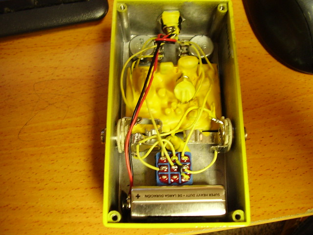
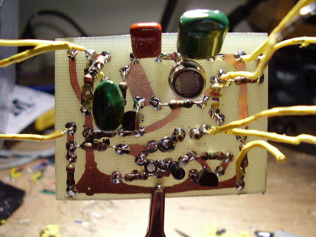
Well KindaFuzzy over at the Freestompboxes forum bought one and took it apart and here's the results:
[Images pinched from KO Amps great Flickr album: http://www.flickr.com/photos/35422385@N07/]
Here's a schematic:
Nocentelli drew up a vero layout too:
As you can see by viewing the schematic it's pretty simple and it's *very* similar to Tim Escobedo's "Wobbletron" circuit as can be seen here (Basically the only real change is the use of a LED/LDR to modulate the vibrato instead of the JFET):
Anyhow, nevermind about that - it sounds nice, build one now :-)
Here's the freestompboxes.org topic discussing it's de-gooping!: http://freestompboxes.org/viewtopic.php?f=7&t=12539
[NOTE] If you want to build a slightly more complex version (But one that can achieve many more tones!) check out MadBeanPedals "QuadraVibe" project here - it's pretty cool : http://www.madbeanpedals.com/projects/index.html [NOTE]


Why is the output resistance 1M5?
ReplyDeleteIt's so high!
It's just a pull down resistor - it's job is to stop switching "pops".
Deleteby any chance would you know how to wire up a simple slow/fast switch like on the bigger version of the magnavibe? thanks
ReplyDeleteRead up on "Phase Shift Oscillators", that's how the LFO on the Magnavibe is implemented - there are a few tricks to alter it's frequency range by altering cap and resistor values...
Deletethank you very much!!
ReplyDeleteThanks for the info on this pedal. The polarity of the three 1u capacitors are not marked on the vero diagram - am I right in thinking that the negative pole of one goes to the base of Q2, the negative pole of the next goes to the 10k resistor, and that the positive pole of the one on the right goes to the 1M5 resistor? Thanks.
ReplyDeleteHow to LFO connection with the Main Photo circuit 4-6
ReplyDeleteLove the info. It's great that you are telling us about these things.
ReplyDeleted drops