
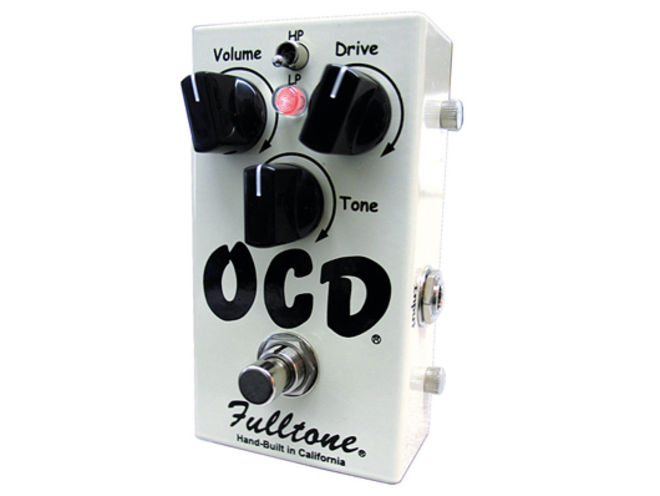
Had a few requests for this, everyone knows what it does and everyone seems to like it. Anyway, here's the description from the Fulltone website:
"AMPS... if you've ever owned a GREAT amp, like a Marshall 18 watt, a VOX AC15 or a Marshall JTM45, and if you have a place where you can crank them up loud, then you know what I'm talking about. Smack a power chord and you (not only) hear the fundamental notes, but you get (count 'em) 4, 5, even 6 additional overtones ringing into a feedback... notes that you can whistle if your ear is good enough! Think Zep'sOcean or Custard Pie or classic tones, including James Gang, the Beatles, AC/DC, Free., and so on.
Back off the guitar's volume and there are a dozen great other sounds at your fingertips... Clean, spanky sounds, with all the highs and lows still intact. And a Tele still sounds like a Tele, a Les Paul like a Les Paul.
PEDALS... (until now) just can't hold a candle to what a good amp can do if you are really picky. You not only lose all the touch sensitivity, but forget about those complex Harmonics. (For me) It's always been somewhat of a compromise using Overdrive pedals... until now. Ladies and Gentleman, I am proud to introduce the Fulltone OCD. I made this pedal for me, but I think you might like it too."
Here's a demo video of the OCD in action;
And here's a schematic for the OCD (V4):
 |
| Fulltone OCD V4 |

As many will recognise this is nothing but a modified version of the Voodoo Labs Overdrive from many moons ago - allbeit a nice sounding one. Check out the Voodoo Labs Overdrive schematic below and compare it to the Fulltone OCD scheme:

The layout and scheme are provided and work of Stratotrasto of the freestompboxes forum! Many many thanks :-) (Notice he also provided the Zendrive project)
For those of you who prefer vero:

Now I get a lot of emails asking me about the differences between the V1, V2, V3 and V4 versions of the Fulltone OCD. Well here is a PDF file that details the differences between OCD V1, V2 and V3 - compare to the above schematic for the V4 differences and you've got all the info you need on the OCD, here it is: http://www.box.com/s/5ef844ca1fbe0571d91d
*NOTE* When building the OCD be careful to check the pinout of your clipping mosfets match up to the layout, also, you can leave out the germanium diode - this was included in V4 prototype but discontinued in the newest models..
**NOTE 2** If you like the OCD, why not try my redesigned "Super OCD", you can find the project file here: http://revolutiondeux.blogspot.co.uk/2012/02/fred-briggs-super-ocd.html
Just built it as per the layout abouve. I have a problem with the gain knob - it does'nt seem that it does a lot. Maxed out - it's just slightly overdriven. Must be something wrong. I used 2N7000's and the 1N34a - same placement as the layout. It's like the gain is the only thing that doesn't work! LP/HP Tone, and Volume work fine.
ReplyDeleteCheck you connections and parts values fully. If your still having trouble get over to freestompboxes.org and post up in the workbench section for the experts there to give you a helping hand!
ReplyDeleteWhat does he mean by 2x10uF? And I'm having a hard time finding a 100nF electrolytic cap at small bear. Is there any problem with using two larger caps in series to give me 100n?
ReplyDeletehello, can you clarify on the pcb, instead of C1, C2, R8, C4, R5, R7 ... thank you
ReplyDeletequote:
ReplyDelete''you can leave out the germanium diode''
I want to do this so I must leave this place empty or use jumper?
Which is the germanium diode?
Aaah what a lovely pedal..built a couple and in a moment of madness I upgraded the 220pf ceramics to silver mica ...wow.. then I replaced the Al/Electrolitics with tantalums and it became a beast...high gain heaven...
ReplyDeleteI too am confused about the caps in the bias circuit. It would make sense to me to have a 100u cap from 9V to GND, like in the Zendrive. But there is also listed 100n and the 2X10uf. I could see having a 10u from VB to GND, but why would you want another from 9V to GND and in parallel with 100u (Making 110uF). I think that makes more sense than 100u in parallel with 100n (100.1uF). Is 2x10u supposed to be from VB to GND, making 20uF? Any help would be appreciated.
ReplyDeleteThat's because real caps behave like inductors at higher frequencies. So the higher the freq you want to atennuate, the smaller the cap needs to be. Google "bypass capacitors" and you'll probably find out more about it.
Delete100uF and the 100n go from +9v to ground. the 2x10uF go from the 4.5v bias to ground - they are not in parallel with the 100uF and 100n. I used 22uF for the 2x10uF caps and it works fine..
ReplyDeletecorrect me if I am wrong...the 100uf elect has the + side to ground on the layout, but the - side to ground on the schem, wich one is correct? I tried both directions on breadboard and it seems to make very little difference...
ReplyDeleteThe 100uF should have it's + to the positive supply and it's - to ground. It is a filter cap used to help filter out noisy power supplies.
ReplyDeletePut this on a breadboard last night and love it! It sounds great! The gain cranks, and the mix of the tone and the LP/HP ad versatility. I didn't use the Germanium diode and I only used a 100uf to gnd (no 100n bc I didnt have one). Thanks much for the info!
ReplyDeletegreat project!! built it and it has a great tube-like OD sound like all FullClone pedals:)
ReplyDeleteI have a porblem with the gain knob, when I crank it up to about to 3 o'clock the sound mutes:S elsewhere it sounds great but I can't reach the high-gain position:S it's great enaough without that:D but this thing kinda annoys me any ideas??
Regarding the 2x10uF question, there ARE two seperate 10uF caps shown on the PCB silkscreen layout. There is only one 100nF cap shown on the PCB, which is located in the feedback loop on the second op-amp. So I suspect that the 100nF shown in +9V supply line may be an error on the schematic, and the 2x10uF (two 10uF caps, side-by-side?) is just drawn on the schematic this way.
ReplyDeleteIt is not unusual to have a large filter cap (100uF) and a smaller filter cap (10uF or less) in parallel on a main power supply leg. This is done to improve HF decoupling. The smaller cap is quicker to respond to fast noise transients than the larger 100uF cap. However, it would make more sense to me to replace the 10uF cap on the 9V leg with the 100nF cap to provide even better HF de-coupling. The 10uF on the 4.5V (op-amp 1 bias) leg provides additional filtering and stability for the bias and the clipping circuits.
As for removing the germanium diode, just replace with a wire jumper.
i replaced the 33k resistor next to the hp & lp switch to a 56k 1/2 watt allen bradley carbon comp resistor. I set my pedal 12 volume 2 tone and 9-10 drive. I found as i increase the tone it does not get trebly it gets more overdriven like a marshall plexi or 1959 amp does when its dimed.This ia what i wanted to do at lower volume levels and it works. i did this to a version 1 ocd. If you try it you will like it, please give me credit for it.
ReplyDeletehi everyone,
ReplyDeletei built ocd exactly like the layout no 2 above but cant get any sound out of it. not even a hum. is the layout number 2 presented above 100% correct?
please help me.
thank you very much.
HI
ReplyDeletedoes anyone have stripboard or perfboard layout?
plase send me to :
iusepolskyeran@gmail.com
Which version of the OCD is this?? thanx greetings from Peru
ReplyDeleteThis schematic and layout is for the V4 OCD, the layout is verified.
ReplyDeletewhere's going the extra cable of the 1 mΩ potentiometer on the top of the schematics
ReplyDeleteIt doesn't go anywhere, the pot is being used as a variable resistor instead of a voltage divider so only two of the three lugs are used.
ReplyDeleteJust built it as per the layout abouve. I have a problem with the Tone knob - it doesn't work. Volume, Gain, LP/HP work fine. Please help !!!
ReplyDeleteSounds like you might have a dud pot, replace the pot and see if it works...
DeleteI have replaced the pot and it works. Thank's man.
ReplyDeletei've used an OA1154 germanium doide instead of the 1N34 and i think this diode is responsible for a loud, high frequencey hum noise, which appears when i crank the pedal up. can i replace it with a jumper, or isn't the diode the problem for the hum?
ReplyDeleteHi, I built this like the vero above It sounds great, however the volume is very low. My vol pot reads 0 Ohm fully maxxed out. Double checked everything, I don get it. Any suggestions?
ReplyDeleteHi, I did the OCD Rev. 4, with this Vero type support (http://solderman.fatabur.se/DCO/ocd_vero_debug.png). I upgraded the ceramics 220pF to Mica and 10µF Electrolitics with tantalums like Nico did and it sounds awesome !
ReplyDeleteKeep Rockin'
Vince
This comment has been removed by the author.
ReplyDeleteIs working now perfect
ReplyDeleteI'm very new to schematics, and I'm curious about a few symbols on the pcb layout. Directly below the drive pot and above the 150k and 10k's there's are unmarked components...are these just jumpers? Also between the above mentioned 10k and 1n there is another unmarked component....
ReplyDeleteThis comment has been removed by the author.
ReplyDeleteI want to make the vero version so I dont have to etch a PCB but I noticed that it has different component values, namely the electrolytic capacitors. They are all 10uf! Is this a mistake or does the circuit function this way as well?
ReplyDeleteContrary to popular opinion that the OCD clipping MOSFETs have their gates connected to the drains, from what I can tell (internet photots), the gates are connected to the sources, which makes the most sense since its the body diodes that are being used anyway (no question about that).
ReplyDeleteIt does not matter if they are connected gate to drain, because the operation is the same, but I'd just like to clear up the misinformation.
Can anyone point me to clear photos showing the OCD PCB traces around the MOSFETs indicating how they are connected?
Drawing of 2N7000's and 1N34A diode are not correct.
ReplyDeleteIm having a problem with the gain pot, it doesnt do anything, i did the vero board exactly comparing it to the stratotasto one, anyone here with a solution?
ReplyDeleteUwaga! W schemacie dla OCD (V4) błędnie oznaczono na rysunku kierunek wlutowania diody Ge 1N34 oraz tranzystorów MOSFET 1n7000. Trzeba je odwrócić!
ReplyDeletePozdrawiam, IrekB
Chodzi oczywiście o rysunek powyższych elementów na płytce. Schemat jest poprawny.
ReplyDeleteIrekB
Linear-IC TL082ACD SOIC-8 Texas Instruments
ReplyDeleteCan i use this IC?
We built the pedal point to point from the schematic and we initially got 60hz hum with tone and gain control working, but no signal. Figuring that the transistors were fried from an earlier attempt we replaced them and now we get no signal whatsoever. Odd problem. Anyone have a clue? The pedal is just a wiring loom at present, so no case but we put in an earth rail in for everything that needed it per the schematic. Am I missing something?
ReplyDeleteHi! I know that this thread is a bit old but maybe someone still reads it :) I got the original OCD version 1.4 and what I can see inside are three 10uF elecrolitic caps and one additional 1uF tantalum cap (marked C8).
ReplyDeleteIt looks like this: https://c1.staticflickr.com/4/3182/3120464055_ebe9d4182e_b.jpg
I can't see any 1uF cap on any of layouts above - where should it go if I wanted to add it to my build?
Works great....took an evening from scratch, including drilling etc...nice tones retained...little issue with grounding at first, but found fault and re-soldered..lovely.
ReplyDeleteThe end of the circuit and take
ReplyDeletethe output from a cap straight from the output of the second.